0-2862-1188
High-tech Injection Molding Software

Highlights
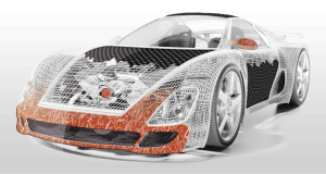
- Developers and designers distinguish possible production problems or critical behavior in the parts long before a real prototype exists. This front loading shortens development times and minimizes risks.
- Tool makers are able to optimally design mold tempering, runner systems, hot or cold runners and ejector packages in the first attempt.
- Molders easily find ideal production parameters to realize the desired part quality and productivity.
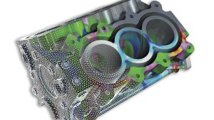
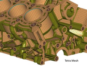
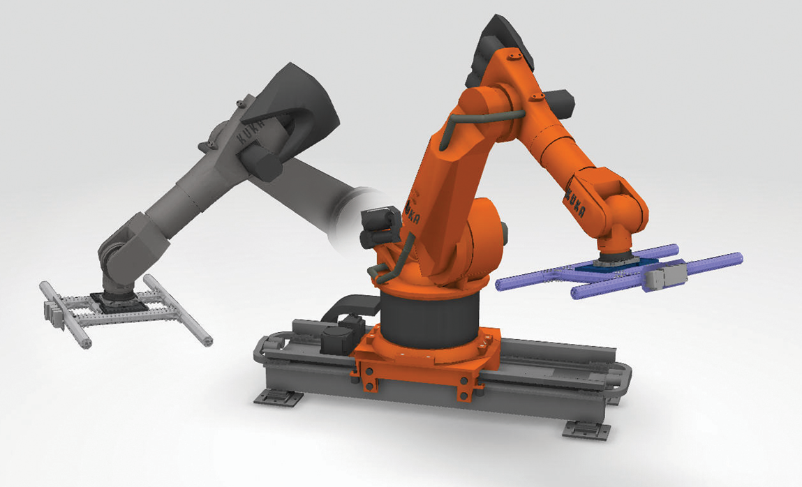
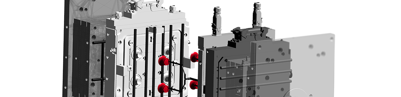
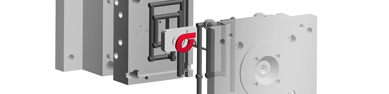
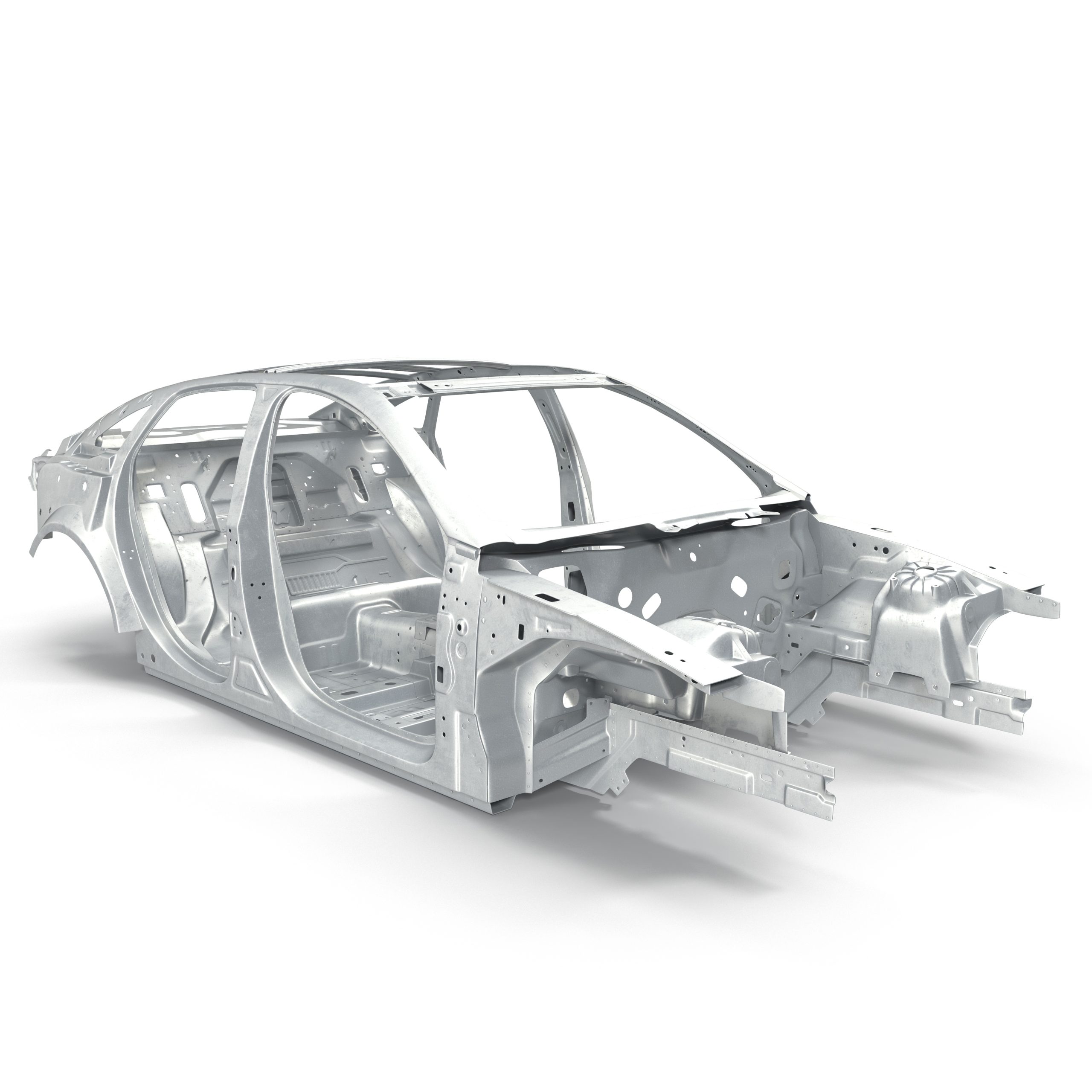
In the majority of cases CAD data are used in developing new parts. These can be loaded in SIGMASOFT® with our CAD-inteface. Whether you have the complete mold with runner and tempering system or, just the part.
SIGMASOFT ประกอบด้วย Applications ดังนี้
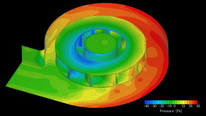
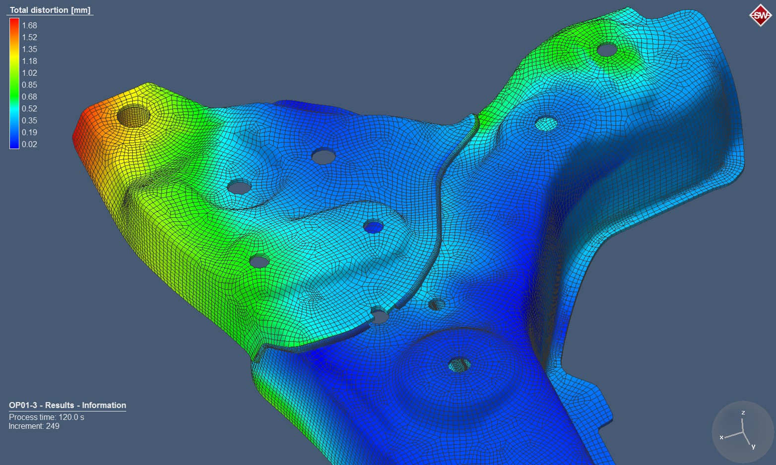
Additional it is possible to export CAD geometries from the SIGMASOFT® Geometry Perspective or distorted geometries from your shrinkage and warpage simulation to your favorite CAD interface.
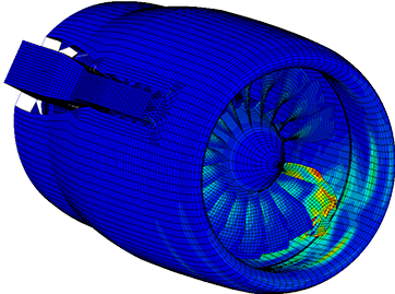
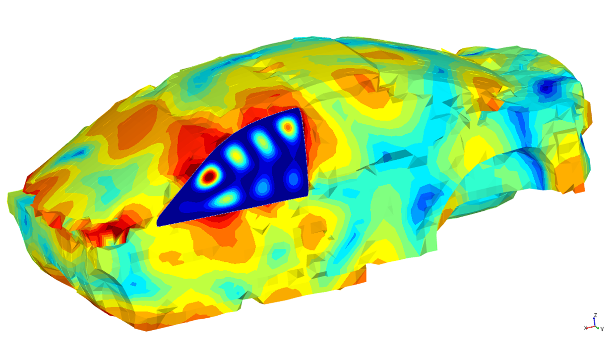
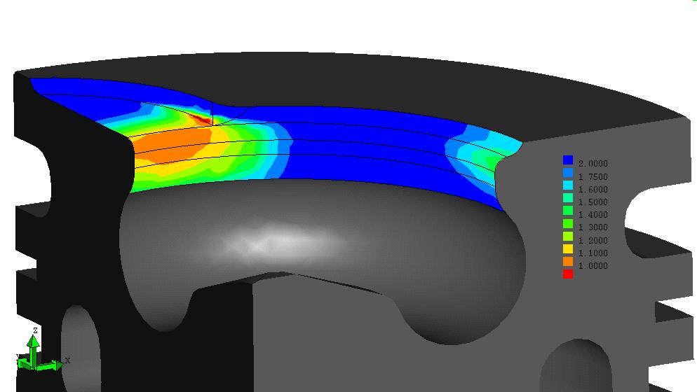
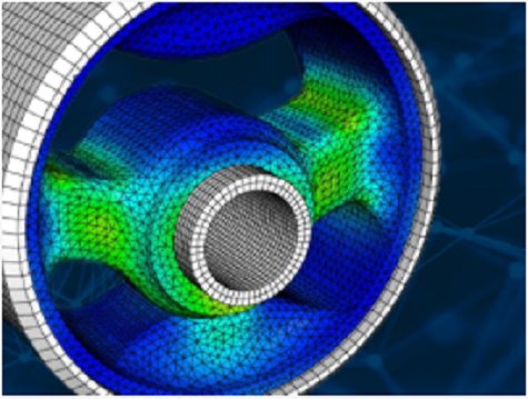
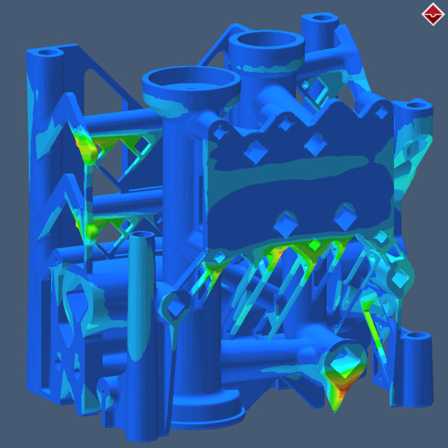
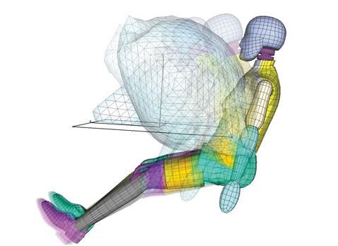
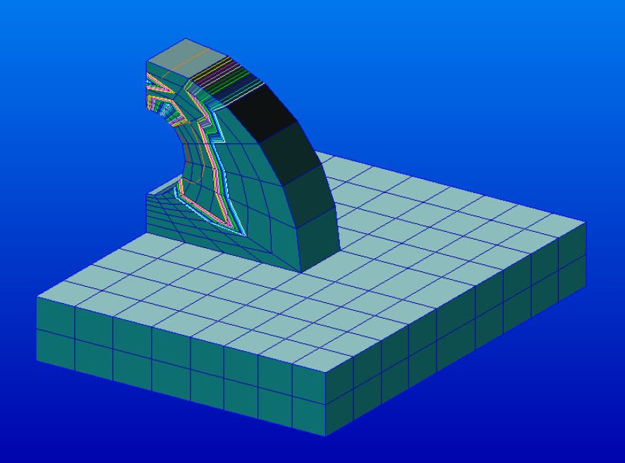
SIGMA LINK is the tool to export the results of SIGMASOFT® polymer system simulation to be used further in FEM-simulation tools (Finite Element Method). The user is free to export every result calculated in SIGMASOFT to his preferred format.
SIGMAlink can use FE meshes for data export, but also for geometry import. Using the same FE mesh for both purposes, the user can exclude later discrepancy between the model used for simulation (which is usually a CAD file) and the FE-mesh used for export. Discrepancy can be in geometry, but also in coordinate system.